Hollow Bricks Firing Kiln Wide Flat Tunnel 950-1050℃ Sintered Temperature
- Category: Tunnel Kilns
- Application: firing hollow bricks
- Output: 70,000 pcs/24 hours
- Size: 162m*8.6m
- Sintered temperature: 950-1050 ℃
Hollow Bricks Firing Kiln Wide Flat Tunnel 950-1050℃ Sintered Temperature
1. Brief introduction
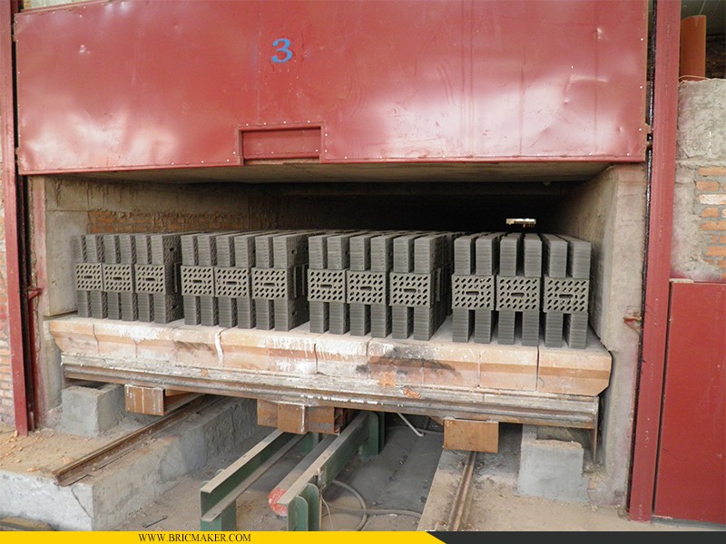
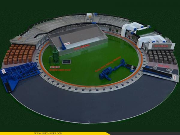
Hollow bricks tunnel kiln is the most popular thermal kiln for the features of continuous working, stable thermal parameters, big output and stable quality. Specially designed for baked hollow bricks, this firing kiln has wider cross-section, shorter cycling of firing and bigger output.
Clay bricks tunnel kiln is composed of kiln body, kiln car and transferring equipment, burning system, air exhaust system, control system, etc.
2. Main technical features
| Kiln type | Flat roof tunnel kiln |
| Sintered product | Hollow bricks / blocks |
| Daily capacity | ≥70,000 pcs per 24 hours |
| Kiln sizes | 162m * 8.6m |
| Kiln cart size | 3.6m*8.6m |
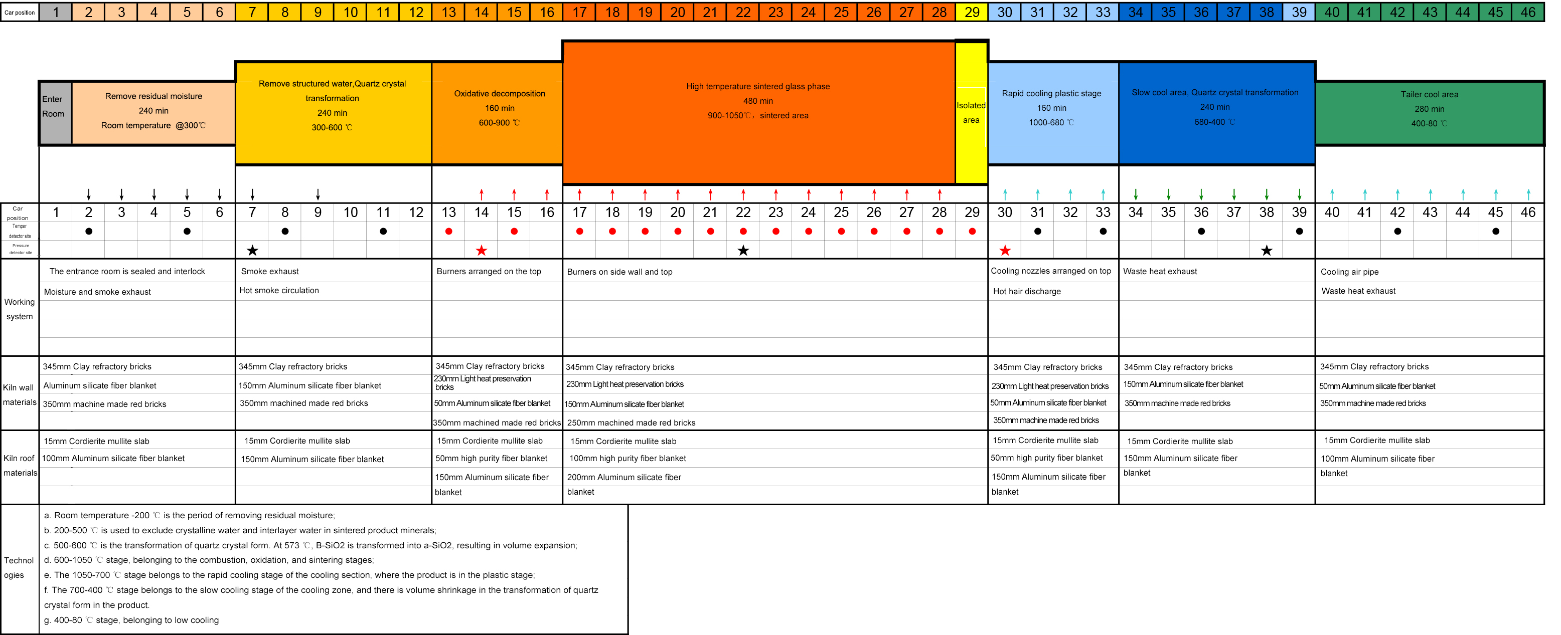
| Qty of kiln cart | Total 68 sets, 45 sets inside kiln |
| Sintered temperature | 950-1050 ℃ |
| Energy consumption | ≤350 Kca/kg |
3. Main structures:
3.1 Kiln body
The entire kiln structure adopts the internationally advanced assembled tunnel kiln manufacturing process, with more standard construction, lighter kiln body, high degree of automation, long service life, and the appearance of the kiln is neat and beautiful.
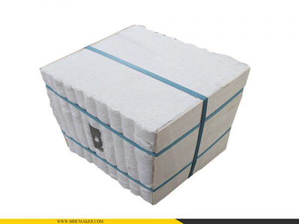
The entire kiln structure is a new flat ceiling structure, the top is made of cordierite mullite ceiling board + aluminum silicate fiber insulation, and the inner wall is made of high-quality refractory brick + aluminum silicate fiber blanket. This structure is tight and air-tight, lightweight, Insulation and durability. The semi-finished steel structure of the kiln body is prefabricated in the factory, and then delivered to the customer site for construction and assembly, which not only ensures the quality of production, but also speeds up the progress of construction and installation.
3.2 Kiln
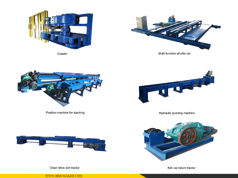
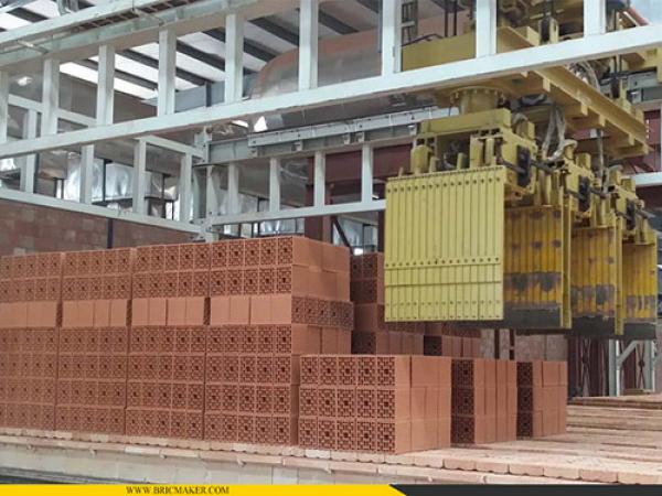
Car & transfer equipment
The overall structure of the kiln car is under the premise of satisfying its load bearing, temperature resistance and reasonable service life. Lightweight materials are used as much as possible to reduce the overall weight of the kiln car, which is beneficial to shorten the firing cycle of the product and minimize the heat loss from the kiln car. The cooling system under the car strengthens the cooling of the kiln car and the track to ensure the normal operation of the kiln car transfer system. The kiln car and the kiln workshop are sealed with two zigzags. The sealing material is aluminum silicate fiber blanket. The kiln car and the kiln wall are sealed with zigzag and sand, and the inside of the kiln is completely isolated from the outside world.
The kiln head is equipped with two automatic lifting kiln doors, and the jacking machine, kiln door and kiln car are interlocked, which effectively controls the infiltration of cold air when entering the car, and ensures the stability of the thermal system in the kiln during the car entering, and it is safe and easy to operate. There is a kiln bottom pressure balance system under the car, which can balance the pressure inside and outside the kiln to ensure a stable firing curve.
3.3 Burning system
The oil circulation return pipeline arrangement is adopted, and the heavy oil coming out of the heater leads to various component pipes on the main pipe on the kiln to supply the oil for the burner. The unused oil in the main pipe returns to the oil tank (or before the oil pump) through the return valve and the oil return line to form a large cycle.
The heavy oil enters the annular main oil pipe from the oil storage tank through the oil pump. A pressure switch is installed on the main oil pipe, and when the oil pressure is lower than the minimum allowable value, a signal will be sent and the fuel supply will be cut off. Corresponding burner groups are provided with annular oil pipes. The fuel oil enters the branch oil pipe through the main oil, valve, filter and flow control valve, and then enters the burner through the manual valve and filter.
Top-fired high-speed burners are used, and the burners are arranged between two brick stacks with a spacing of 1800mm. The pre-burning area is designed in 4 groups (8 rows of 48 burners), and each burner is equipped with a flame detector, automatic ignition device, solenoid valve, needle valve, etc. There are 24 groups in the firing area (192 pieces in 24 rows on the top, 16 pieces in 4 groups on the side walls). All burners are managed centrally by the computer system.
3.4 Air exhaust and circulation system
Air exhaust system is composed of smoke exhaust fan, bracket, air pipe and electric gate valve. Low temperature and high humidity gas and flue gas enter the exhaust branch pipe, enter the branch pipe, main pipe and fan in turn, and are discharged through the chimney at high altitude or imported into the waste heat system to supply the drying kiln.
Waste heat recovery system (2 sets of waste heat fans, high temperature and low temperature) is composed of low temperature waste heat recovery and high temperature waste heat recovery, the low temperature part is mainly used to recover the waste heat after 650 ℃ in the kiln, and the temperature is 200-250 ℃; the high temperature part is used to recover the rapid cooling zone, and the temperature is about 400°C. After the two parts of waste heat air enter the main pipeline and mix, they are sent to the drying kiln through the waste heat fan, and are equipped with brackets, air pipes and electric gate valves.
Starting from No. 2 parking spaces behind the firing area, a fast cooling zone is set up, equipped with 5 rows of 40 rapid cooling nozzles.
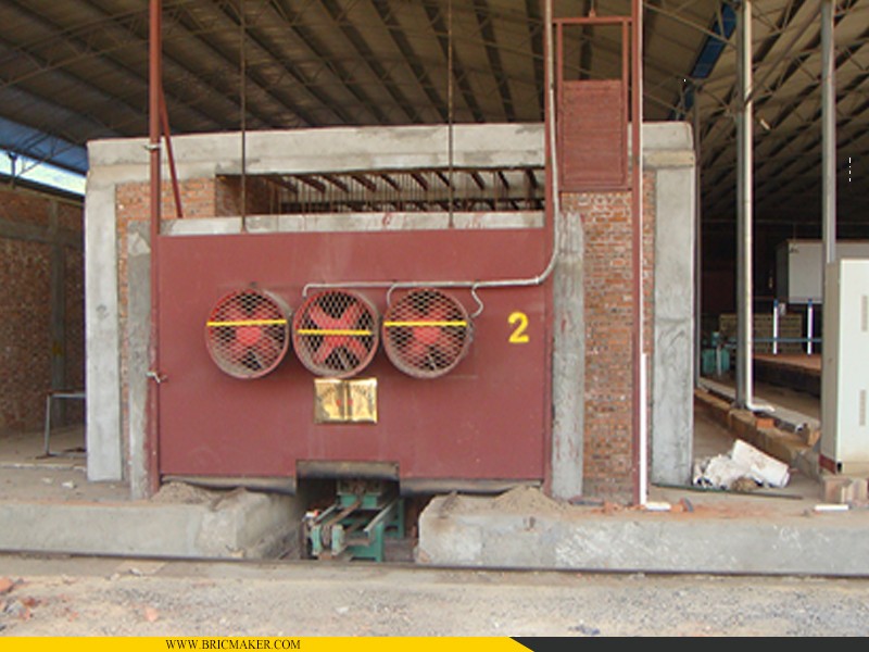
3 sets of axial flow fans are arranged before and after the cooling area for blowing air under the vehicle.
A set of axial flow air is arranged before and after the pre-burning area, which is used to extract the heat under the car, and the waste hot air is brought into the waste heat recovery system.
INQUIRY
CATEGORIES
- Automatic Clay Brick Production Lines
- Rotary Tunnel Kiln
- Tunnel Kilns
- Vacuum Extruder
- Green Brick Cutting Group Transfer System
- Brick's Robot Auto Stacking System
- Brick's Raw Material Process Machines
- Aging Warehouse Equipment
- Red bricks load & package machine
- Kilns' Refractory Materials
- Desulfurization tower
CONTACT US
Name: General Manager
Mobile:+8613151630928
Whatsapp:+8613222235952
Email:sales@bricmaker.com
Add:No.1, Huayu Road, Donglai Development Zone, Zhangjiagang City, Jiangsu, China